Mid-Autumn Festival is a day of reunion for us. In order to welcome the Mid-Autumn Festival, and at the same time thank the employees for their hard work to Meis
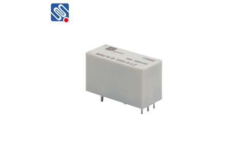
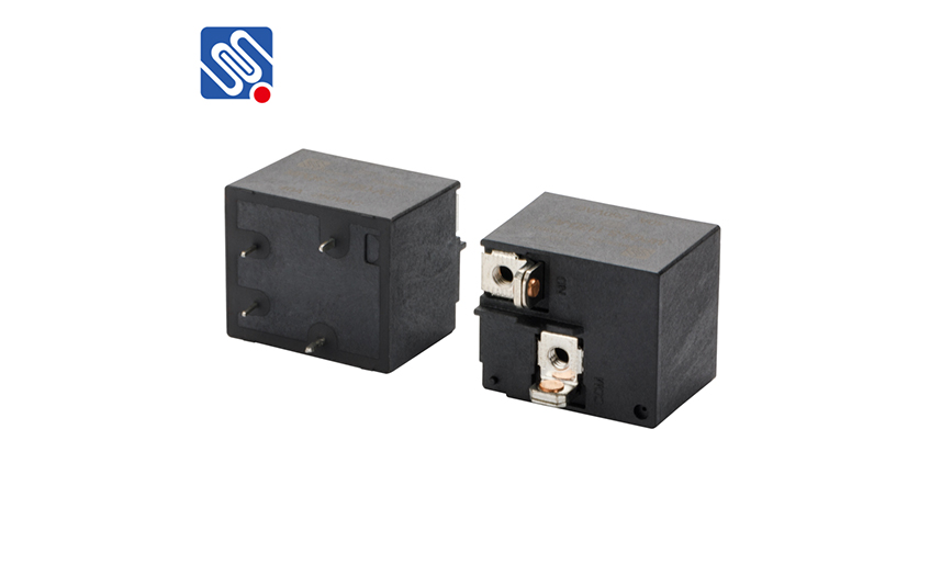
10A NO DC12V PCB Relay
CONTACT PARAMETERS
Contact Arrangement: 1A
Contact Material: Silver Alloy
Rated Load:
10A 250VAC/30VDC(阻性Resistive)
5A 250VAC/30VDC(阻性Resistive)
3A 250VAC/30VDC
Electrical Life: 1×10⁵ 次 OPS
Mechanical Life: 1×10⁶ 次 OPS
绝缘电阻 Insulation Resistance | 1000MΩ(500VDC) |
介质耐压 Dielectric Strength | 触点与线圈间Between Coil & Contacts: 4000VAC 1min |
断开触点间 Between Open Contacts: 1000VAC 1min | |
动作时间 Operate Time | ≤10ms |
释放时间 Release Time | ≤10ms |
环境温度 Ambient Temperature | -40℃~+105℃ |
振动 Vibration Resistance | 10Hz~55Hz 1.5mm 双振幅 |
冲击 Shock Resistance | 稳定性Functional: 100m/s2(10G) |
强 度Destructive: 1000m/s2(100G) | |
引出端方式 Terminal Form | 印制板式 PCB |
封装形式 Construction | 塑封型Sealed, 防焊剂型Flux proofed |
重量 Unit Weight | 约Approx. 3g |
CHARACTERISTICS
COIL DATA(23℃)
额定电压 Rated Voltage VDC | 动作电压 Operate Voltage VDC | 释放电压 Release Voltage VDC | 最大允许电压 Max Allowable Voltage VDC | 线圈电阻 Coil Resistance Ω±10% | 线圈功耗 Coil Power W |
5 | ≤3.75 | ≥0.25 | 7.5 | 125 | 约Approx. 0.2 |
6 | ≤4.5 | ≥0.3 | 9 | 180 | |
9 | ≤6.75 | ≥0.45 | 13.5 | 405 | |
12 | ≤9 | ≥0.6 | 18 | 720 | |
18 | ≤13.5 | ≥0.9 | 27 | 1620 | |
24 | ≤18 | ≥1.2 | 36 | 2880 |
APPROVALS
安全认证Approvals | UL | TUV | CQC |
证书编号 Certificate Number | E313266 | R50217035 | CQC11002059553 |
负载 Rating | 5A 250VAC/30VDC 3A 250VAC/30VDC 1/10H 277VAC/250VAC | 5A 250VAC/30VDC 3A 250VAC/30VDC | 5A 250VAC/30VDC 3A 250VAC/30VDC |
ORDERING INFORMATION
MPR | -S | -1 | 12 | -A | ||
产品型号 Model:: | MPR | |||||
产品结构 Structure: | S: 塑封型 Sealed 无Nil: 防焊剂型 Flux proofed | |||||
触点组数Contact Group: | 1 : 1 组 1 Group | |||||
线圈电压Coil Voltage: | 5、6、9、12、18、24VDC | |||||
触点形式Contact Form: | A: 常开NO | |||||
OUTLINE DIMENSIONS,W IRING DIAGRAM AND PCB LAYOUT(单位Unit: mm)
Outline Dimensions


PCB Layout(Bottom View) Wiring Diagram

REMARK:
1) In case of no tolerance shown in outline dimension: outline dimension ≤1mm, tolerance should be ±0.2mm; outline dimension >1mm and ≤5mm, tolerance should be ±0.3mm; outline dimension >5mm, tolerance should be ±0.4mm;
2) The tolerance without indicating for PCB layout is always ±0.1mm.
PERFORMANCE CURVE
Maximum Switching Power Electrical Endurance Curve





 selena
  sales@msrelay.com
 13968707033
 +86-577-62518811


